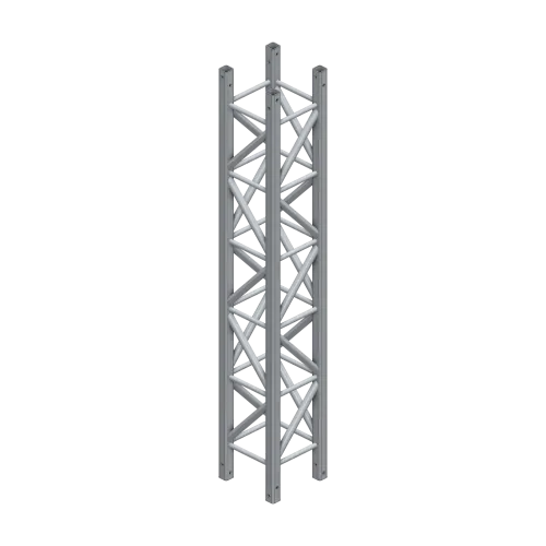
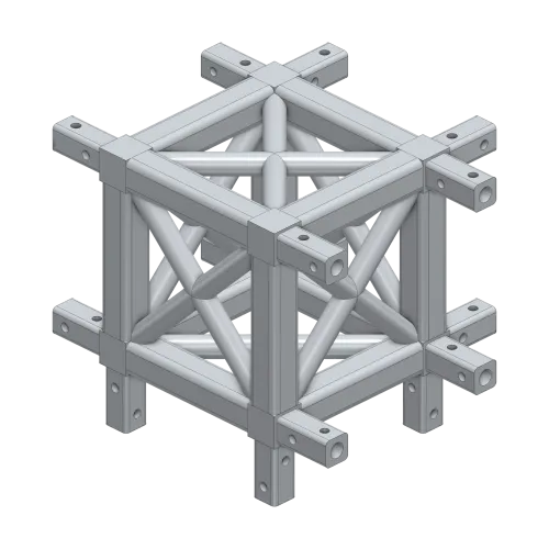
AML500 Base Plate - Socket, Spigot
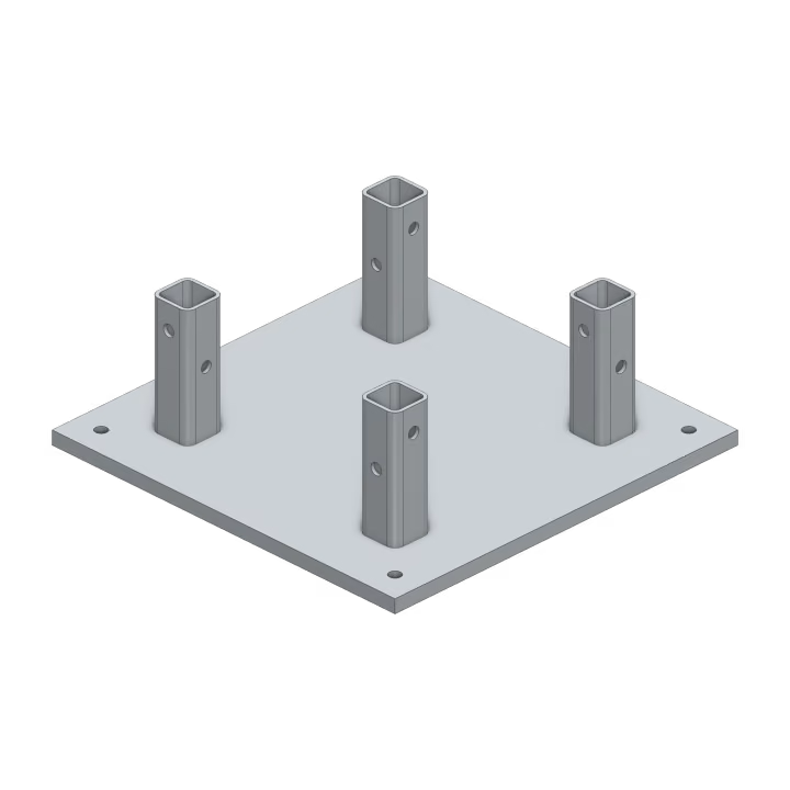
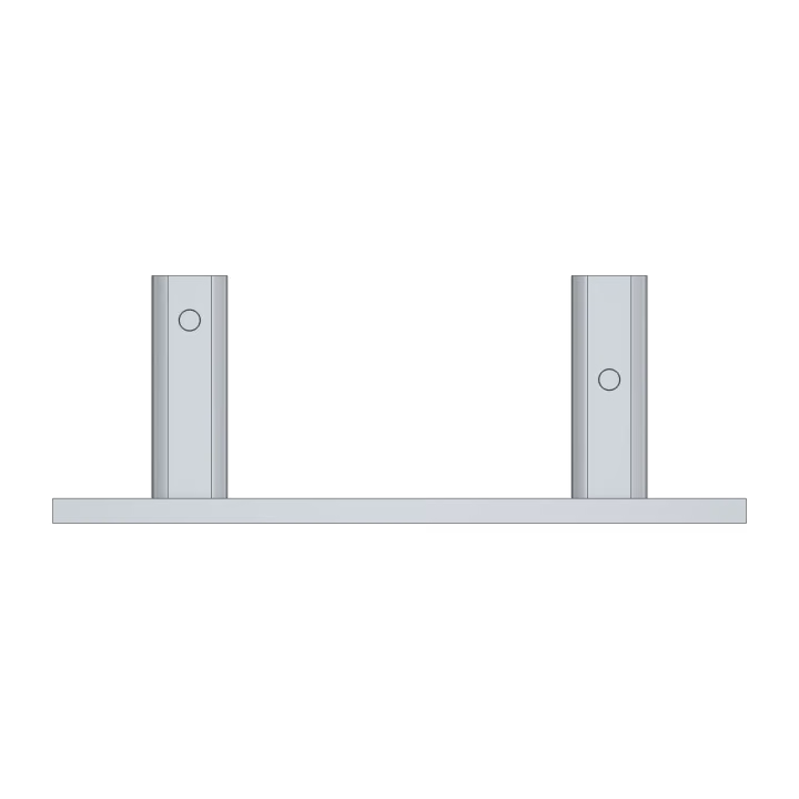
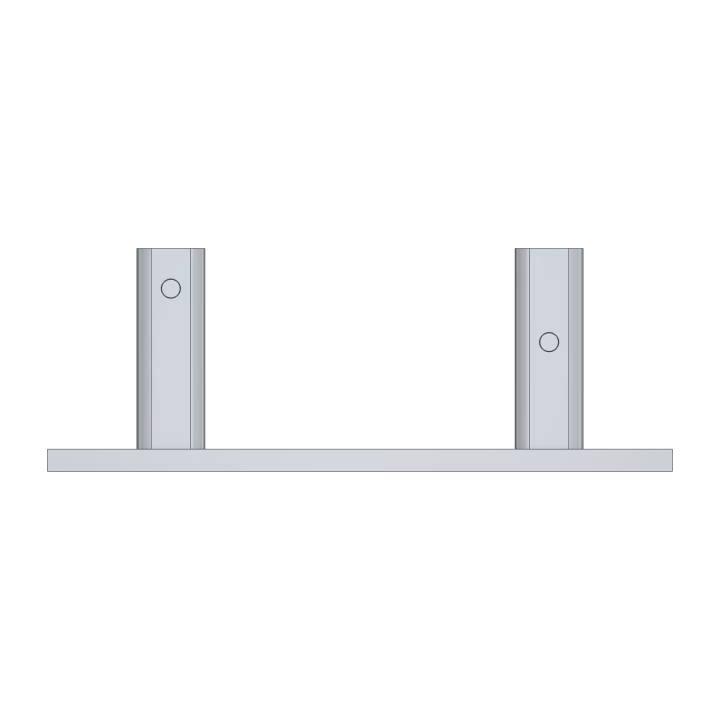
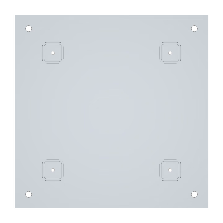
AML500 base plates fix the foot of an AML500 leg or tower to a concrete footing. Each is a 700 mm square, 25 mm 5083 aluminium plate with four 76.2 x 6.35 mm SHS chord stubs welded on, their tops machined as a module end with the same taper-reamed holes. Four Ø22 mm holes at the corners, on a 600 mm square, take M20 anchors (supplied by others), and a drain hole under each stub lets water out.
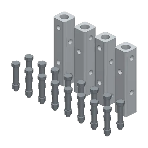
The socket base (AP-AML500-BP-SK) takes a node directly, bolted with an AP-AML500-JK-MN joint kit, or a module, joined with an AP-AML500-JK-MM kit as at a module joint. The spigot base (AP-AML500-BP-SP) comes with four joint spigots fitted and bolted in its stubs, so a module slides straight on and bolts up with an AP-AML500-JK-MN kit. Both put the joint 250 mm above the footing, so the lattice in the leg stays on the 500 mm grid from the ground up.
Anchors and footings are engineered for each project.
Specifications
Physical Specification
Interfaces
Installation / Attachment
| Quantity | Mounting | Notes |
|---|---|---|
|
4
|
Anchor Bolts
|
Four M20 anchors on a 600 mm square into a concrete footing (by others)
|
Available Interfaces
| Quantity | Interfaces | Notes |
|---|---|---|
|
1
|
AML500 Spigot Joint
|
A node's fixed spigots (AP-AML500-JK-MN kit) or a module with loose spigots (AP-AML500-JK-MM kit)
|
Subcomponents
Subcomponents
| Quantity | Item | Materials | Material Finish |
|---|---|---|---|
|
1
|
25 mm Base Plate, 700 mm Square, 4 Anchor Holes, 4 Drain Holes
|
Aluminium 5083-H116
|
Mill Finish
|
|
4
|
76.2x6.35 SHS Chord Stubs, Machined and Taper-Reamed as a Module End
|
Aluminium 6061-T6
|
Mill Finish
|
3D Preview
Equipment in the AML500 System